
SpF®
Implantable Spinal Fusion Stimulators

Overview
About the Device
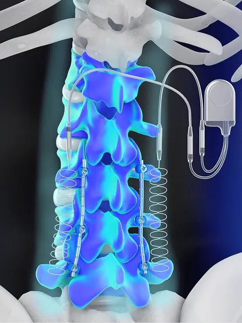
The SpF® Implantable Spinal Fusion Stimulator is an FDA-approved, class III, surgically implanted, battery-powered direct current (DC) bone growth stimulation device designed to promote bone healing following spinal fusion surgery. The device’s cathodes are implanted on each side of the desired fusion site during the procedure, which provides consistent, around-the-clock stimulation to increase the probability of a successful spinal fusion outcome.

Features & Benefits
The first and only bone growth stimulation implant to support spinal fusion outcomes with no need for patient compliance.
The cathodes are placed precisely along each side of the targeted fusion site offering controlled treatment directly to the area where patients need it most.
Provides constant, around-the-clock therapeutic treatment, providing surgeons and patients the best opportunity for successful healing outcomes.
Powered by pre-clinically proven Direct Current technology
Clinically proven improved clinical outcomes
How the SpF® Stimulator Works
The SpF® stimulator delivers safe, effective and clinically proven direct current stimulation through a pair of titanium cathodes. The cathodes are placed on each side of the fusion site, and the generator is implanted away from the cathodes during surgery. The area between and around the cathodes safely and effectively stimulates the body’s natural healing mechanisms to promote bone growth.
Clinical Effectiveness & FDA Approval
The SpF® stimulator is supported by pre-clinical research and published clinical studies demonstrating its safety and effectiveness in improving spinal fusion outcomes.
The SpF® stimulator has demonstrated an overall (clinical and radiographic) success rate of 96% in instrumented lumbrosacral fusions. 1+
Device Specifications
Technology: Direct Current (DC)
Original FDA Approval Date: 1988
MRI Conditional Conditions: at 1.5 & 3.0 Tesla
Model: SpF® PLUS-Mini
- Signal: 60 µA
- # of Levels: 1 – 2 Levels
Model: SpF®-XL IIb
- Signal: 40 µA
- # of Levels: 3 or More Levels

Is the SpF® Stimulator Right for You?
The SpF® Stimulator is ideal for patients undergoing spinal fusion surgery who have certain risk factors or a history of failed fusion.
It is prescribed and implanted by spine surgeons as part of a comprehensive spinal fusion treatment plan.
Frequently Asked Questions
Ready to Start Healing?
Ready to support your spine fusion recovery with the SpF® stimulator?
INDICATIONS
The SpF® PLUS-Mini is indicated as a spinal fusion adjunct to increase the probability of fusion success in 1 or 2 levels. The SpF®-XL IIb is indicated as a spinal fusion adjunct to increase the probability of fusion success in 3 or more levels.
USAGE
SpF® devices have only been studied as an adjunct for lumbar spinal surgery.
DESCRIPTION
The SpF® PLUS-Mini is a solid state constant current generator producing a constant current of 60 microamperes and is powered by one lithium manganese dioxide battery. The electronics and power source are hermetically sealed within a titanium generator case – an area of approximately 600 mm2 is platinum coated and functions as the anode. The SpF® PLUS-Mini lead wires consist of two 15 cm leads of drawn brazed strand (DBS) wire covered with silicone and connected to the generator by a titanium connector. The cathodes are available in preformed wave and mesh configurations. In the preformed wave configuration, each lead is terminated in a 12 cm (4 cm preformed wave) uninsulated triple strand titanium wire which acts as a cathode and is connected to the insulated DBS lead by a titanium connector which disconnects at both the generator and cathode. The mesh cathode consists of two strands of titanium wire woven into a flexible grid with nominal dimensions of 1 cm x 4 cm. The SpF®-XL IIb is a solid-state constant current generator producing a constant current of 40 microamperes and is powered by one lithium manganese dioxide battery. The electronics and power source are hermetically sealed within a titanium generator case – an area of approximately 400 mm2 is platinum coated and functions as the anode. The SpF®-XL IIb lead wires consist of two 15 cm leads of drawn brazed strand (DBS) wire covered with silicone and connected to the generator by a titanium connector. The cathodes are available in preformed wave 14 Physician’s Manual and Full Prescribing Information and mesh configurations. In the preformed wave configuration, each lead is terminated in a 24 cm (8 cm preformed wave) uninsulated triple strand titanium wire which acts as a cathode and is connected to the insulated DBS lead by a titanium connector which disconnects at both the generator and cathode, or is permanently connected with a titanium crimp (fused lead configuration only). The mesh cathode consists of two strands of titanium wire woven into a flexible grid with nominal dimensions of 1 cm x 8 cm.
CONTRAINDICIATIONS
Any case where SpF® stimulators could come into contact with metallic implant components (i.e., those that contain Titanium, Cobalt Chrome and Stainless Steel). Any surgical implantation procedure such as minimally invasive surgical MIS procedures requiring the SpF® cathodes to be disconnected from their corresponding leads prior to or during implantation since this may seriously compromise the electrical performance of the implantable stimulator’s cathodes to deliver a constant current to the fusion site as intended.
WARNINGS
Do not use with defibrillators.
PRECAUTIONS
Electrosurgery Electrosurgical instruments are capable of producing radio frequency voltages of such magnitude that direct coupling can occur between the cautery tip and lead system of the generator. To preclude the possibility of burning of tissues adjacent to the electrode or damage to the generator electronics, electrosurgical equipment should not be used on the patient in the vicinity of the generator after the stimulator has been implanted.
Diathermy
Therapeutic diathermy should not be used in the treatment of a patient who has an implanted stimulator, since this equipment can produce voltages, which may cause damage to the electronics. Diathermy must never be applied over the site of any bone stimulator implant since high currents induced in the electrode lead will cause burning of the tissues in contact with the electrode tip.
Handling
The energy source and electronics of the generator are well protected within the generator case and will be unaffected by normal handling. However, the possibility of damage by mechanical shock, such as a drop onto a hard floor, cannot be precluded. Any unit subjected to this type of accident should not be implanted. Do not disconnect the leads from the cathodes during the surgical procedure. Use with Internal Fixation. If the stimulator is used in conjunction with metal internal fixation devices, no metallic part of the stimulator should be allowed to come into contact with the fixation device.
Placement of Generator
To avoid patient discomfort, care should be taken to place the generator in a comfortable tissue pocket so the rising of the skin contour is avoided or minimized.
Placement of Cathodes
The cathodes of the implantable spinal fusion stimulator must be positioned a minimum of 1 cm from the nerve roots to reduce the possibility of nerve excitation during a MRI procedure.
MRI SAFETY INFORMATION
Artifacts Testing and Efficacy
1.5 Tesla MRI Safety Information SpF® PLUS-Mini and SpF®-XL IIb Models Experiments conducted to assess magnetic field interactions, artifacts, and operational aspects of the implantable spinal fusion stimulators combined with experience in patients indicate that MR procedures may be performed safely in patients under the following conditions: • MR static magnetic field of 1.5 Tesla. • Maximum spatial gradient 250 gauss/cm for the SpF® PLUS-Mini model and maximum spatial gradient 450 gauss/cm for the SpF®-XL IIb model. • Gradient magnetic fields of 20 Tesla/second. • Maximum whole body averaged Specific Absorption Rate (SAR) of 1.1 W/kg for 25 minutes of imaging. 16 Physician’s Manual and Full Prescribing Information MRI procedures must only be performed according to the following guidelines: • Plain films (radiographs) must be obtained to assess the site of the implanted SpF® stimulator prior to the MRI examination to verify that there are no broken leads present. • If this cannot be reliably determined, then the potential risks and benefits to the patient requiring the MRI examination must be carefully assessed in consideration of the possibility of excessive heating to develop in the leads. • The patient must be continuously observed during the MRI procedure and instructed to report any unusual sensations including any feelings of warming, burning, or neuromuscular excitation or stimulation. • If these occur, the MRI procedure must be discontinued. Static Magnetic Field of MR Systems A patient with a SpF® device may safely undergo an MRI procedure using a shielded MR system with a static magnetic field of 1.5 Tesla (maximum spatial gradient 250 gauss/cm for the SpF® PLUS-Mini model and maximum spatial gradient 450 gauss/cm for the SpF®-XL IIb model). Gradient Magnetic Fields of MR Systems Pulse sequences (e.g., echo planar imaging techniques or other rapid imaging pulse sequences), gradient coils or other techniques, and procedures that exceed a gradient magnetic field of 20 Tesla/second must not be used for MRI procedures. The use of unconventional or nonstandard MRI techniques must be avoided. Standard or conventional pulse sequences (e.g., spin echo, fast spin echo, gradient echo, etc.) may be used for MRI examinations. Radio Frequency (RF) Fields of MR Systems MRI procedures must not exceed exposures to RF fields greater than a whole body averaged specific absorption rate (SAR) of 1.1 W/kg for 25 minutes of imaging. The use of unconventional or non-standard MRI techniques must be avoided. Physician’s Manual and Full Prescribing Information 17 MRI Artifacts Artifacts for the SpF® stimulators have been characterized using a 1.5 Tesla MR system (maximum spatial gradient 250 gauss/cm for the SpF® PLUSMini model and maximum spatial gradient 450 gauss/cm for the SpF®-XL IIb model) and various pulse sequences. This information is indicated on the table that follows. Based on this information, implantation of the SpF® stimulator (i.e., with reference to the center of the device) a distance of at least 5-8 cm from the imaging area of interest is likely to maintain the diagnostic quality of the MRI examination. Artifact size is dependent on the type of pulse sequence used for imaging (e.g., larger for gradient echo pulse sequences and smaller for fast spin echo pulse sequences), the direction of the frequency encoding direction (larger if the frequency encoding direction is perpendicular to the device and smaller if it is parallel to the device), and the size of the field of view. Positional errors and artifacts on MR images may be larger for MR systems with static magnetic field strengths greater than 1.5 Tesla or smaller for MR systems with lower static magnetic fields strengths using the same imaging parameters. Implant the SpF® stimulator as far as possible from the spinal canal and bone graft is desirable since this will decrease the possibility that artifacts will affect this area of interest on MRI examinations. The use of fast spin echo pulse sequences will minimize the amount of artifact associated with the presence of the SpF® stimulator compared to the use of other imaging techniques. The implantable spinal fusion stimulator was positioned parallel to the static magnetic field of the MR system for all conditions indicated below. MRI was performed using a 1.5 Tesla MR system (maximum spatial gradient 450 gauss/cm). Signal void values are indicated in millimeters squared.
References:
- Rogozinski, A. and Rogozinski, C. Efficacy of Implanted Bone Growth Stimulation in Instrumented Lumbosacral Spinal Fusion. Spine (Phila. Pa 1976), 1996. 21(21): p. 2479-83.
+ The original clinical study which led to PMA approval in 1987 yielded an overall success rate of 81% SS&ED.